Sample Display Screens
GuiMod,s GX Device Add-on
Please be aware that the below screen shots are for the GUIMods Package – you first must install Package manager and then install GuiMods so that the below screens will appear – also once you have added GuiMods the settings can be accessed under display on the GX device. See more details about GUIMODS after the setup-helper description
This addon is NOT supported by Victron energy in anyway.
Also please be aware that this add-on does not change the original GX devices coding it just enhances the screen displays – all the usual GX device firmware update’s still occur as normal – and you can always turn GuiMods off in the settings and return to the standard Victron screen display or even uninstall its changes completely


New GX device display screen Addon - SetupHelper also includes a GUI based package manager
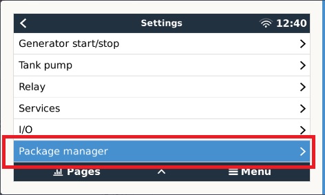
Made and Authored by Kevin Windrem The SetupHelper package provides: a mechanism to automatically reinstall packages following a Venus OS update an automatic update mechanism to keep packages up to date from GitHub archives or USB stick control of the automatic download and install from the GUI add and remove packages from the system manual download, install, uninstall from the GUI a "blind" install of SetupHelper from SD/USB media backup and restore SOME settings from the GX device SetupHelper is also required for other packages made by Kevin Setuphelper must be installed BEFORE running the other package setup scripts How to Install setuphelper by Blind Install: By far, the easiest way to install SetupHelper is the "blind install" which requires no command-line interaction. 1) Download venus-data.tgz from the SetupHelper GitHub repository. 2) copy it to the root of a freshly formatted Fat 32 SD card or USB memory stick ( max size 32Gb) 3) place the media in the GX device's sd card slot. (Cerbo, CCGX, etc) 4) reboot the GX device TWICE - allowing the system to display the GUI each time after the second reboot, you should find the Package Manager menus at the bottom of the Settings menu 5) REMOVE THE MEDIA from the GX device VERY IMPORTANT to prevent the next reboot from starting the process all over again failure to do so could disable re installs following a Venus OS firmware update !!! CAUTION: if you are a advanced programmer or have added other software add ons.
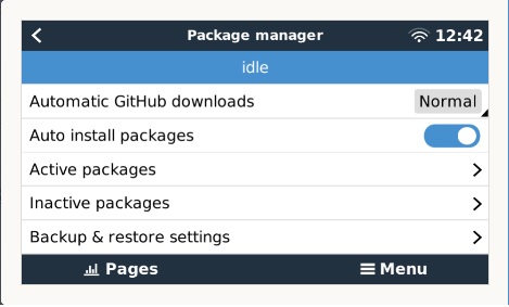
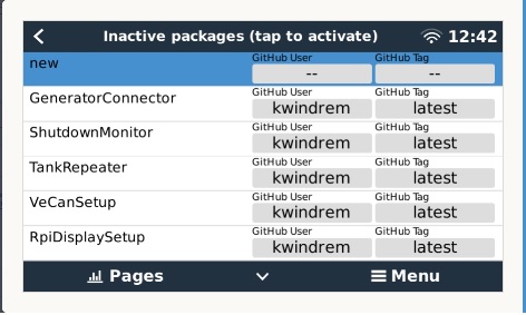
This mechanism overwrites /data/rcS.local !!!! If you are using rcS.local to perform boot-time activities, /data/rcS.local must be recreated following this "blind" install Note that SetupHelper also uses /data/rcS.local for re-installation following a firmware update so use caution in recreating rcS.local. venus-data.tgz is available here: Once SetupHelper is installed, updates to it and other packages can be performed through the GUI using the Package Manager menus. CAUTION: Package Manager allows uninstalling SetupHelper. This can not be undone since the menus to control Package Manager will go away You would need to use the Blind Install again to reinstall SetupHelper Note that removal does not actually remove the package so other setup scripts will continue to function. Description: There are two parts to SetupHelper: 1) Package Manager, controls automatic and manual updates to packages 2) Utilities used by other packages' setup scripts. These resources simplify the task of writing install/uninstall scripts and may be of help to others writing packages of their own. The latter is of concern only to those writing new Venus modifications or modifying an existing setup script. These are described in detail later in the Setup Helper Description document. Package Manager: The Package Manager includes a set of menus on the GX device menu system that allows the user to view package versions, control automatic package updates and manually install, uninstall, add and remove packages. A python program runs in the backgrounds (as a service) to do the actual work and to interface with the menus. Package Manager menu: The first line of this menu provides status for Package Manager, indicating what it is currently doing Automatic GitHub downloads controls if packages are automatically downloaded from GitHub. This occurs if a newer version is available. Modes: Normal checks GitHub for a package once every 5 minutes and waits 10 minutes after a download has occurred before checking another Fast checks GitHub for a package once every 5 seconds (10 seconds after a download), then after one pass through all packages, the downloads are switched to Normal rate Once checks GitHub for a package at the fast rate, but only once, then downloads are turned off Disable disables GitHub downloads Auto install packages: Controls whether new versions of a package are automatically installed. Some users may wish to have the system automatically download new updates, but install them manually. In this case, automatic GitHub downloads may be turned on and Auto install packages turned off Auto install packages also influences whether packages transferred from SD/USB media are automatically installed or just transferred to local storage Active packages: displays all active packages Version information is displayed for each package: Git Hub shows the version found on GitHub Stored shows the version stored on the GX device Installed shows the version actually installed and running Tapping on one of the entries leads to the Package editor menu Inactive packages: displays all INACTIVE packages I.e., default packages not yet activated or manually removed The first entry is always "new" and allows the operator to enter package name, GitHub user and branch/tag from scratch Additional lines (if any) are default packages (from the default Package List file) If a package is already added to the version list, it will not appear in the Add Package list Tapping on one of the entries leads to the Add Package menu Backup & Restore settings: saves settings to the settings Backup file on removable SD/USB media restores from same /data/SetupHelper/settingsList is a complete list of settings saved to settingsBackup GuiMods SetupHelper ShutdownManager SOME Victron stock settings in the following sections Alarms CGwacs DigitalInputs Generators Gui Pump Relay System SystemSetup Vrmlogger Any logo files in /data/themes/overlay The parameters must exist to be saved The parameters must exist to be updated during a restore Note: Victron is working on a more comprehensive mechanism but is not working reliably yet This part of PackageManager is temporary and will be removed when the Victron functionality is working Package editor: This menu facilitates: manual install, uninstall, package add and package remove changing GitHub access information for each package Normally, you would want to download the latest released version but you may also wish to try out a beta version or revert to a previous one. Once the GitHub branch is changed, PackageManager will update the GitHub version and, if enabled, download this alternate version. Remove Package Packages that are of no interest to you may be removed from Package Manager. Removed packages will no longer appear in the version list or be accessible from the Package Editor menu. But you can add the package back in manually. Add package menu: Allows the package name, GitHub user and GitHub branch or tag to be entered. Pressing Proceed initiates the package add. The package will be added to the package list (and appear in the Package versions menu) only IF the name is unique Pressing Cancel returns to the default package list All three fields must be set appropriately or you'll see -- for the GitHub version Package Manager does not allow removing packages unless they are uninstalled first. Package Manager DOES permit uninstalling SetupHelper, however this will remove the Package Manager itself. Once removed, the Blind Install mechanism will be needed again !! USB/SD updates: When the GX device is not connected to the internet, a USB flash drive or microSD card provides an install/upgrade path. To use the USB update process Navigate to the GitHub, repo, click on tags and select the appropirate branch or specific version tag. Choose the .tar.gz download link. (Do not download from the Code tab or download the .zip file. These won't work.) Copy the archive file to a USB memory stick or microSD card. Do NOT unpack the archive Repeat this for all packages you wish to install. (These can all be placed on the same media along with the SetupHelper venus-data.tgz file) Insert the stick in the GX device. If SetupHelper has not yet been installed, follow the Blind Install process above. Once Package Manager is running, it will transfer and unpack the archive files and update the package list with the new packages. If Auto install packages is turned on, the packages will then be installed NOTE: no version checks are made for packages found on SD/USB media! Package Manager is quite content to transfer and install an older version! So make sure you have the latest version especially if your GX device does not have internet access.
GuiMods Description details below
GuiMod's Information
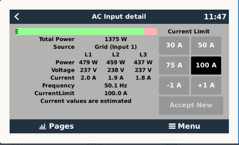
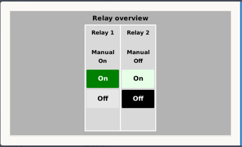
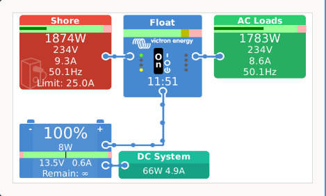
Some GuiMods Details are below. The enhanced Hub overview includes voltage, current, frequency and input current limit values. The enhanced Grid Parallel flow overview which presents most components in the system but lacks room for any detail. Only total power plus a gauge indicating power on each leg/phase is shown on the overview. Configuration settings can be found in: Device List / Settings / Display & language/ GuiMods This package provides the following modifications to the Venus OS GUI: Grid Parallel Flow overview: Tiles have been reduced in size to make room for all components. Except for the battery, only a gauge and a total power number are displayed Additional details are displayed on full screens devoted to that part of the system. Tapping the center of the tile on the overview screen brings up the details. When entering the enhanced flow overview page, target areas are displayed for a few seconds with a message instructing "tap for details" Hub Flow overview: This overview provides the tiles for AC in and out, inverter, battery, Solar (PV) charger and in some cases PV inverters. The Grid Parallel overview is a better choice if this overview hides components due to limited real estate. In the stock code, different flow overviews were used depending on the system type (e.g, ESS active). In this version, the user may choose between the enhanced Grid Parallel and simpler enhanced Hub overviews. Add tank information (both overviews) 4 tanks fit along the bottom of the page for more than 4 tanks, the list scrolls Add temps information (both overviews) A combination of up to 4 tanks and temps fit across the bottom For more, the bottom row splits into separate rows for temps and tanks Each row scrolls horizontally if more than 4 items exist in the row Move Settings and Notifications to the top of the Device List page Optionally hides the Tiles Overview Enhances the Mobile Overview all new layout and tile organization add Inverter Only mode shows voltages current and frequency for AC in and out shows current for DC loads shows solar voltage and current hides Pump switch if not enabled to make more space for tanks (this became standard in v2.70~9) tanks column scrolls if there are more tanks than space allows add temperate sensors to tanks column The tanks column is split into separate columns for tanks and temperature sensors A common tile height is set for both columns, then each column is filled in separately Any tank that appears as a dBus temperature sensor should appear Adds VE.Direct inverter status and control Enhances the Tank Tile red indicates low/high fluid levels indicates NO RESPONSE if no signal received from tank tile shrinks if needed to show more tanks, then list scrolls display custom tank names (stock in v2.70~9) displays absolute fluid quantity (e.g., gallons) in addition to percentage Adds VE.Direct inverter status and control Uses custom tank name if it exists and optionally shorten tank names beginning with Venus v2.70~16, NEMA2000 tank names can be too long to fit in available space enabling this option will shorten the tank name to the first two words (first word for compact tank tiles) and replace "Waste" with "Gray" to be consistent with "Black" label for sewage tank Adds a Relay Overview page that allows controlling all relays. Previously, relay control is several menu levels deep so this is much faster Status for all relays is also shown along with the function (manual, generator, pump, alarm) Buttons presented for pump and generator affect the actual parameters for those devices, not just the relay state. A relay name has also been added. This name is shown on the Relay Overview. The name scrolls if it won't fit in the available space. All relay configurations are in Device List / Settings / Relay. That menu has been expanded to set names and control whether the relay is shown on the Relay Overview. Note that for the Alarm function, there are no controls, yet the current alarm state is show. Pump control has three modes: On, Off and Auto which is controlled by the associated tank level. Generator control has buttons for Manual Start and Manual Stop as well as Auto Enable which toggles the enables the condition-based run control Note that if condition-based run is enabled, Manual Stop may not stop the generator. But turning off Auto Enable would cause the generator to stop. each of these enhancements/modifications can be selected individually any time (while system is running) via the Settings Display GuiMods menu Power Gauges The power gauges provide an indication of the inverter's and battery's ability to satisfy the AC and DC loads and help the user to manage system loads. Power gauges for inputs and outputs provide an indication of current power levels relative to user-defined limits. Again, providing some help in system management. Gauges registering in the red region suggest an overload will occur if loads are not reduced immediately. Gauges registering in the yellow region suggest an overload may occur some time in the future. The inverter gauge is the main indicator of system health. It will indicates an inverter overload more clearly than the AC input and output gauges could. Showing power at multiple locations in the system permits the user to more easily identify the needed correction. Power gauges display power for each leg of the system as separate horizontal bars. The AC input has a finite power limit based on the input wiring and breaker. An adjustable input current limit further restricts available AC input power. The gauge in this tile reflects the AC input current limit setting so the power at the system input is shown relative to this input. The AC output power is a combination of AC input power and that provided by the inverter. The AC output power gauge ranges are set by a user-defined limits The AC output distribution may have it's own limit (e.g., the panel's master breaker). The gauge is set to this limit so the user can identify a potential breaker trip. The battery too represents an area of concern. If it is overloaded, the system will shut down. Many systems include DC loads which draw power from the battery, so it is important to provide an indication of how much DC power is being extracted from the battery relative to it's maximum discharge current. The system also charges the battery so power flow may also be into the battery. Therefore, the battery gauge must indicate a charging or discharging current. The zero point is therefore in the middle of the gauge with discharging to the left and charging to the right. The PV (solar) charger and inverter tiles represent power supplied by these devices. Again, user-defined limit sets the range of the gauge. The DC System tile shows the combination of Loads and charging sources (such as wind) connected to the battery. Details pages repeat the associated gauge(s) and provide more detail for that area of the system. Where possible, voltage, current and frequency for each leg of the system are shown in a table. The Inverter detail includes inverter mode selection: On, Off, Inverter only, Charger only, Eco. The AC input detail includes a set of buttons to set the input current limit. The PV charger detail provides a system total as a gauge and power number, then lists each charger showing its name, power and the PV array voltage. The PV inverter detail provides system totals for grid and output connections then lists name, total power, power for each leg and where the inverter is connected (input or output) The system does not provide current values for the AC input and output of the system. AC input and output details pages show current values that are calculated based on the power and voltage. With a low power factor, actual current values could be significantly higher those shown. Configuration All configuration is done through the main menu system. Go to Device List / Settings / Display & language / GuiMods Changes to any of these settings are immediately seen on the overviews. (Previous versions of GuiMods required running the setup script again to make changes.) Show Tile Overview controls whether the Tile Overview is shown in the Overview rotation Move Settings to top of Device List Normally, these items appear at the bottom of the Device List Turning this option on moves them to the top Show boat & motor home overview is a duplication of the button in the Display & language menu as a convenience since it interacts with the next button Use Enhanced Mobile Overview When on, the standard mobile overview is replaced with the enhanced version provided with this package. Details are explained above Use Enhanced Flow Overview Replaces the standard flow overviews with the enhanced version described above Use Grid Parallel Enhanced Flow Overview Selects between the simpler Hub and more complete Grid Parallel overviews. Use Enhanced Flow Overview must be on to see and change this option Show tanks on Flow Overview Show temperatures on Flow Overview Fluid levels and temperatures are displayed at the bottom of the Flow Overview when the associated switch is on. Combine AC input/output loads The enhanced flow overview displays two load tiles: Loads on Input and Loads on Output. Confusion is likely especially when a system only connects to one load output. This option combines the information into a common tile in the upper right of the overview and changes the title to AC Loads. Show Loads On Input Not all systems have loads connected to the input side of the inverter/charger. This would include loads connected to the AC 2 output. To avoid confusion, this option allows you to hide this tile when it is not being used. (There is no mechanism to automatically hide this tile.) Shorten tank names When on, tank names are shortened to one or two words depending on the available space. In addition "Waste" is replaced with "Gray" to be consistent with "Black" and in line with common RV terminology. AC Input Limit Preset 1 - 4 Provides rapid selection of common AC input current limits through the popup accessed by touching the lower portion of the AC input tile. A preset is active for any value other than 0. For 0 the preset button disappears. If you wish to set a preset to the inverter's minimum current limit, specify a value of 1 for the preset. Temperature Scale Selects either °C or °F (or both) for temperatures displayed on the Flow and Mobile Overviews. Time format Selects the time format for the Enhanced Mobile and Enhanced Flow overviews: 24 hour, 12 hour with AM/PM or don't show time at all Inactive Tiles on Flow Overview Inactive tiles can be hidden, shown or shown dimmed Automatic GitHub updates If SetupHelper is up to date, this item controls automatic updates from GitHub Normal - enables updates at a rate of 1 package check every 10 minutes Fast - enables updates at a rate of 1 package check every 10 seconds after all packages have been checked once, Normal mode is automatically selected This mode is handy for making a quick check to insure all packages are up to date, then allowing the system to check again at the slower rate Check packages once - makes one pass through all installed packages at the fast rate then disables automatic updates Disabled - prevents the system from checking GitHub for updates Access level must be set to Installer or above to change this setting. Package Versions moved to the SetupHelper package and now appears in its own menu: Device List / Settings / Package Versions The move was so that the versions and automatic updates could be controlled even if GuiMods was not installed Power Gauges leads to a second menu Show power gauges When on, power gauges are inserted in the AC input and output tiles, The Multi icon, the Battery tile and the PV Charger tile. Access level must be set to Installer or above to change the following gauge limits. Inverter peak power is the maximum power the inverter can produce for a limited amount of time. This is the maximum power displayed on the gauge The inverter spec sheet will list this as "peak power" For some inverters, this value is double the continuous value, so you may wish to set this to a lower value in order to favor more space to display lower values. Inverter caution power is the maximum power the inverter can produce under the best conditions (low temperature, etc.). This is the transition between yellow and red regions on the gauges. The inverter spec sheet will list this as the maximum continuous power at low temperature. Inverter max continuous power is the power the inverter can produce indefinitely. This is the transition between the green and yellow regions on the gauges. The inverter spec sheet will list this as the maximum continuous power at the highest operating temperature. Max power Loads on Output is the maximum power accepted by devices that will be powered by the inverter. For example, this is could be the power equivalent to the AC breaker. If you do not want this limitation, set the value to 0. Max power Loads on Input is the maximum power accepted by devices that will be powered only by Grid/Shore power. If you do not want this limitation, set the value to 0. Grid feed-in limit provides the gauge range for power flow INTO the AC input of the system. Generally, this should be 0 unless ESS has been configured to feed energy into the grid. Note there are other system settings that control the actual grid feed-in. This parameter is ONLY for the gauge and is provided because feed-in logic is very complex. Max power Multi/Quattro charger is the maximum power the charger portion of the inverter will DRAW from the AC input. This is generally close to the Continuous Power above but may need some experimentation to display properly without showing an overload. Note that the gauge will show power to the left of the zero line when it is charging the battery or when it is supplying the DC system loads. Max PV charger power is the maximum power expected by all PV chargers in the system. Max power PV inverter on AC Input is the maximum power expected from all of the PV inverters tied to the grid side of the system Max power PV inverter on AC Output as above for the PV inverters attached to the output side of the system. Max battery discharge current is used for the battery gauge and is the maximum sustained battery draw. Max battery charge current is used for the battery gauge and is the maximum sustained battery charging current. This parameter, used only for the battery gauge has been added, but should generally be set to the same value as the DVCC max charge current. It should be set the same as the DVCC max charge current if DVCC is used. Max DC load power is the maximum of all DC loads in the system. This is usually the DC main breaker/fuse size in amps multiplied with the DC voltage. So a 60 amp main breaker on a 12 volt system would be 720 watts. If there are no DC loads, set this value to 0. Max DC Charger power is the maximum lf all DC charging sources such as a DC-DC converter from the starter battery or a wind generator. Set this parameter to the expected maximum for all charging sources. The last two parameters also affect the naming of the DC System tile. If the DC Charger power is set to zero but the DC load power is not zero, tile will read DC Loads If the DC charger power is not zero but the DC load power is zero, the title will read DC Chargers Otherwise, the tile will have a name of DC System indicating there are both loads and charging source. Installation: This script should be run manually initially. It will then called from reinstall Mods to reinstall functionality after a Venus update The easiest way to install GuiMods is to use do "blind install" which installs from an SD card or USB stick without any terminal interaction: 1) Download venus-data.tgz from the GitHub repo. 2) Install the setuphelper package 3) place the media in the GX device (Cerbo, CCGX, etc) Follow the instructions in the setuphelper area CAUTION: This mechanism overwrites /data/rcS.local !!!! If you are using rcS.local to perform boot-time activities, /data/rcS.local must be recreated following this "blind" install Note that SetupHelper and GuiMods2 also use /data/rcS.local for re-installation following a firmware update so use caution in recreating rcS.local.